Exact Metrology, a comprehensive metrology service provider, participated in a webinar on February 20, 2020. The general subject involved testing and inspecting parts that are 3D printed. Josh Schradin, a project manager at Exact Metrology, gave a presentation on industrial CT (Computed Tomography) for additive manufacturing.
A CT scan, also known as an X-ray Computed Tomography (X-ray CT) or a Computerized Axial Tomography scan (CAT scan) uses computer-processed combinations of several X-ray images taken from different angles to produce cross-sectional (tomographic) images or “virtual slices” of specific areas of a scanned object. This allows the user to see inside the object without cutting or damaging it.
The reconstruction process takes multiple images of the object at multiple angles or projections around the object. With a projection, users can analyze the part formation or look for defects. Once the complete projections are captured through a 360-degree rotation, the images are segmented into grayscale value pixels.
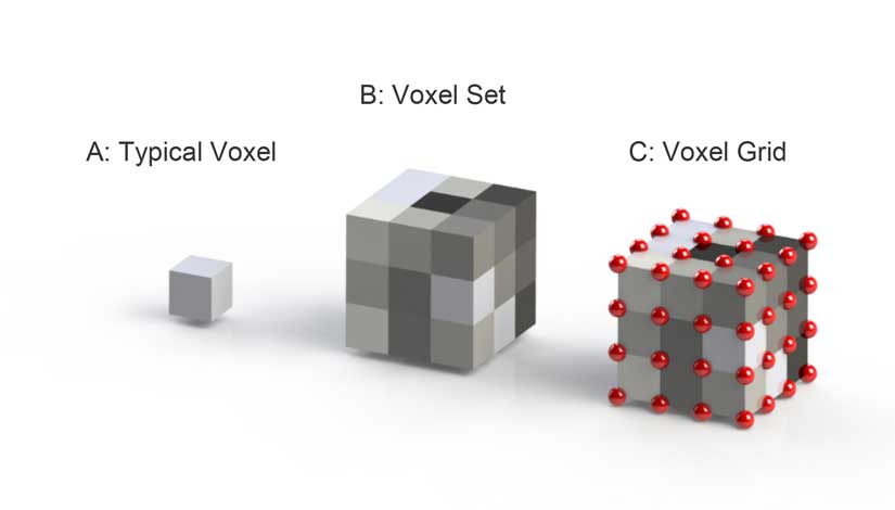
Since the same theoretical point was captured from multiple angles, they become 3D volumetric pixels, or voxels. A voxel set features different colors based on density and grayscale value. A voxel grid is used to stich images together.
Magnification is also an important part of CT scanning. Moving the object closer to the X-ray source provides a larger shadow, optimizing the resolution of the final image, while having an object closer to the detector provides a smaller shadow that decreases the final resolution.
Applications of CT scanning in the additive world include defect analysis/porosity, dimensional analysis, trapped powder, product content position, reverse engineering wall thickness, air gap detection and others. In defect analysis, exploring the complete volume of an object allows users to see defects that would normally go unnoticed. Volume of voids, or porosity, can be calculated to determine risk of mechanical failure.
Users can align the data to the CAD model, export the defects out and run finite element analysis and/or simulation. Many specs have a defect size limit. CT scanning assures that limit isn’t surpassed.
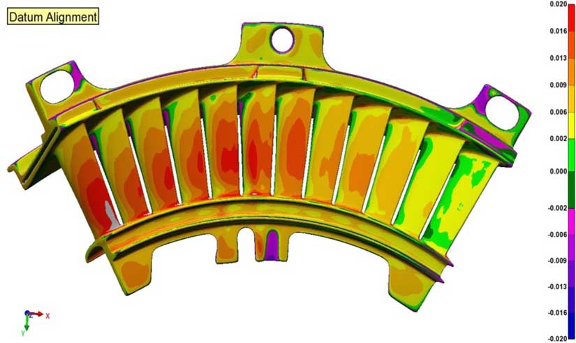
CT data can be used to measure dimensions from a drawing to verify that a part is within specifications. A color plot deviation to the nominal model is also helpful to verify a part is meeting specifications. Many samples of a part can be run to determine a trend. In addition, a metal part can be scanned prior to heat treat and after heat treat to see what has changed. A heat map is also applicable for deviations in wall thickness and air gap.

Trapped powder can be located during the printing process either by magnification or using a color map that shows deviation to the nominal model.
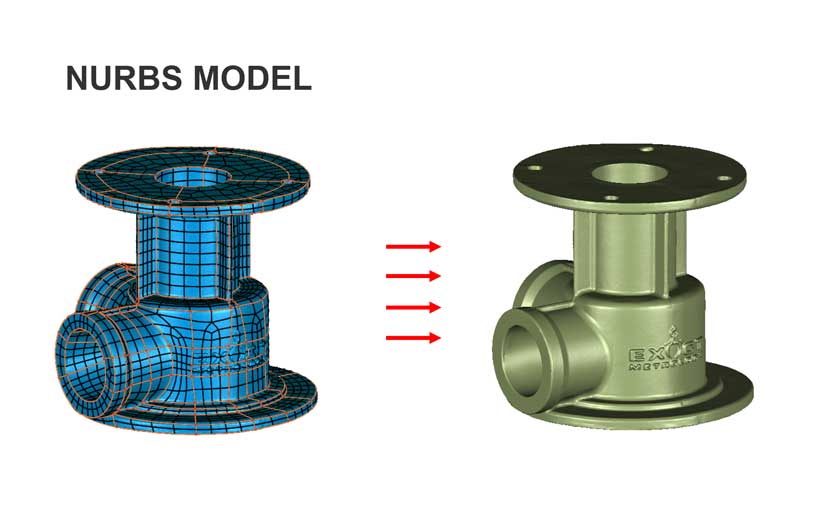
Reverse engineering is achieved with the NURBS model, which stands for ‘Non-uniform rational B-Splines.’ This model consists of a curve network applied directly to a mesh controlled by allowable fit tolerances (see image 10). The final surface skin represents the CAD surface used and can further facilitate downstream applications such as machining, FEA, build corrections etc. Applied to a watertight mesh, it will result in a solid model.
Product content position allows manufacturers to audit their products and determine if embedded objects are placed properly.