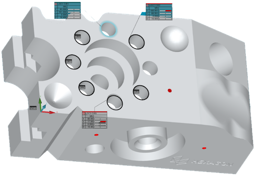
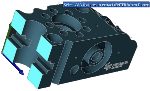
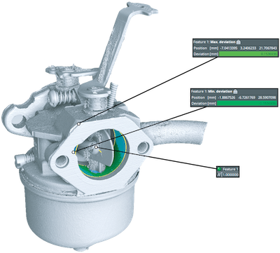
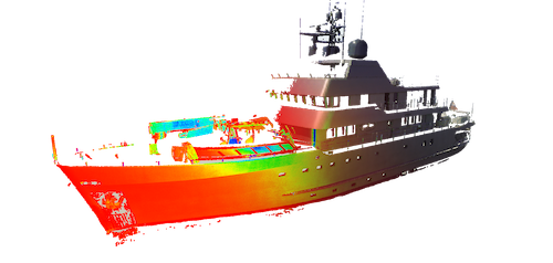
Just touch to begin! There’s no need to navigate through menus. The user is guided through a full set of inspection tools, such as construction of features or feature sets, 2D and 3D dimensional reporting. PC-DMIS Touch has the power and functionality to make what should be simple… simple.
Feature Recognition PC-DMIS Touch will decide which features are geometrically possible based on the points collected and highlight any possible features from the point set, such as circle and plane. The operator can then choose the matching feature to be measured.
Run measurement routines easily: All arm measurements are recorded. Run as many times as you like.
Feature Construction tasks are completed by a simple, consistent workflow.
PC-DMIS Touch helps the user either:
GD&T functionality is built in and includes: Flatness, Roundness, Cylindricity, Concentricity, Straightness, True Position, Parallelism, Perpendicularity, and Angularity
PC-DMIS Touch organizes measurement plan features intuitively by “Face”--a new concept for the traditional work-plane-- and also guides the user through automated alignment sequences depending on the available feature types.
For instance, a Plane-Line-Point alignment is completed by either measuring all three features, selecting previously measured features from the list or graphics display, or a combination of both.
As features are measured the user selects whether or not to display all or part of the corresponding data on the report while at the same time updating feature nominal and tolerance data.
Instant access to the repor tis available with a statistical view of how the measured features are stacking up against their respective tolerance requirements.
Reports are created automatically during the part measurement ans all measurement reports are saved separately from the measurements themselves.
An ideal complement to many 3D inspection systems, in a fraction of the normal time it allows you to: